uSEQ Build Guide
This is probably classes as an easy build, although there are a few things to be careful with (marked in green). Most of the components are already pre-assembled on the PCB, so you just need to solder knobs, switches and headers and mount the panel.
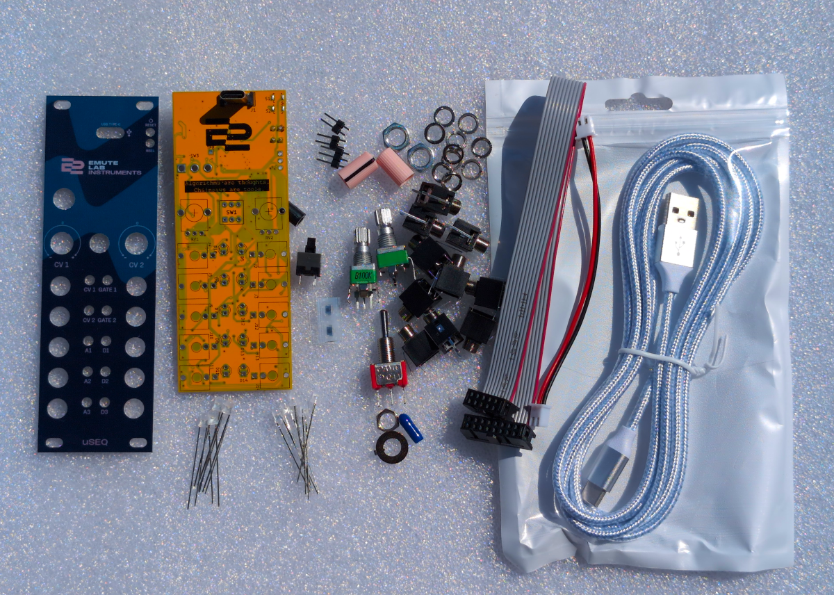
In the kit
- PCB, with most of the components pre-soldered
- aluminium face plate
- power cable
- 2M USB-A to USB-C cable
- 2 pin expander cable (for future firmware releases)
- 5 pink LEDs
- 5 ice blue LEDs
- 2 2-pin headers
- 3-pin header
- 2 surface mount momentary buttons
- 10 sockets
- 2 100k potentiometers
- momentary switch
- toggle switch
- 2 potentiometer caps
- momentary switch cap
- toggle switch cover
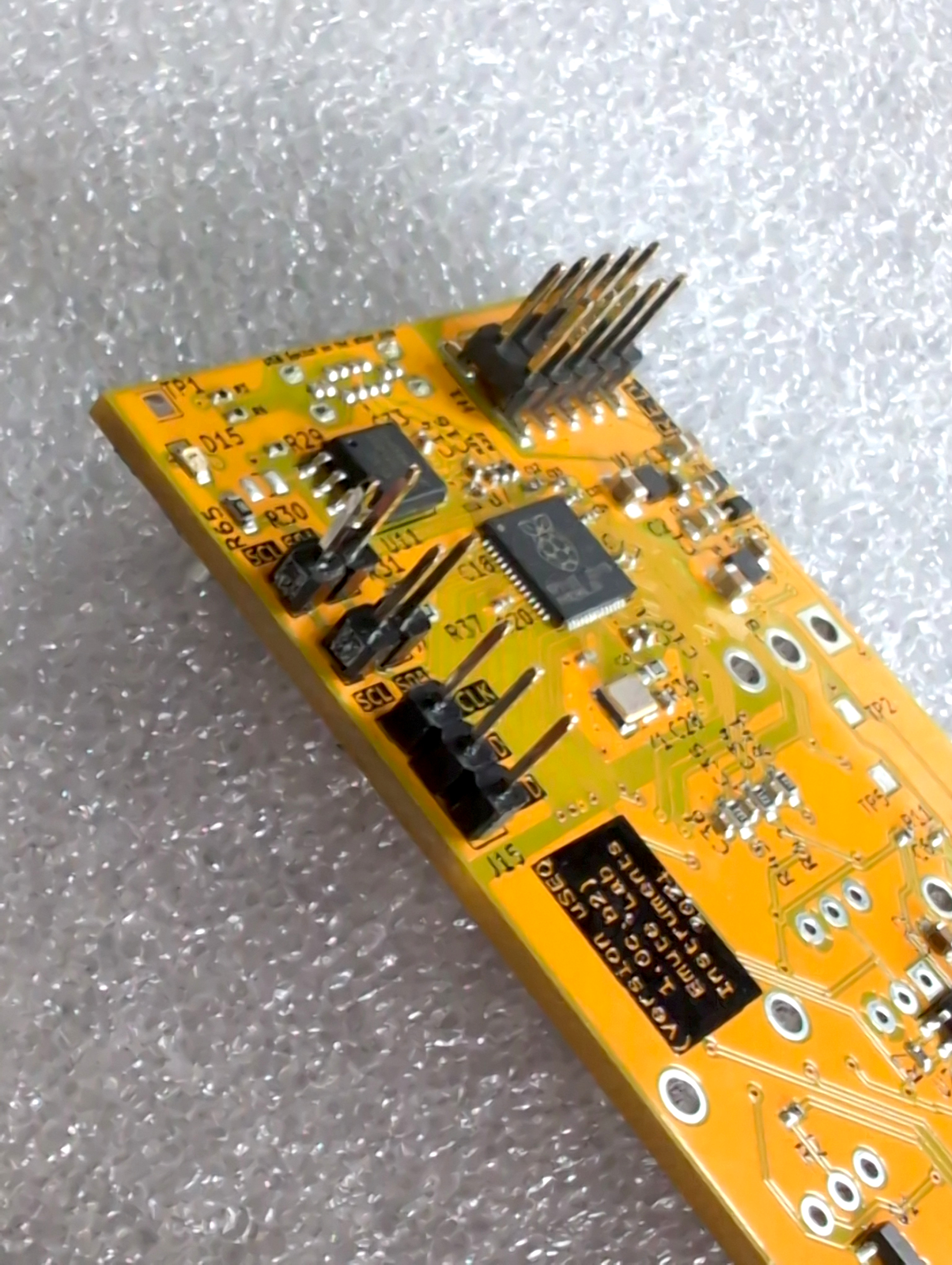
About the PCB
The top part of the PCB is a small and very basic computer - a Raspberry Pi RP2040 microcontroller, some flash memory, a clock crystal, a USB connection and power conditioning. The lower two-thirds of the board is mostly op-amps and transistors that deal with analogue inputs and outputs for the computer. When you send code to uSEQ, you are telling the computer what to do with these inputs and outputs.
You will need:
- Soldering equipment
- Tweezers
- Cutters
Building uSEQ
Step 1: Headers
Solder on the 2 x two pin expansion port headers and the 3 pin JTAG header
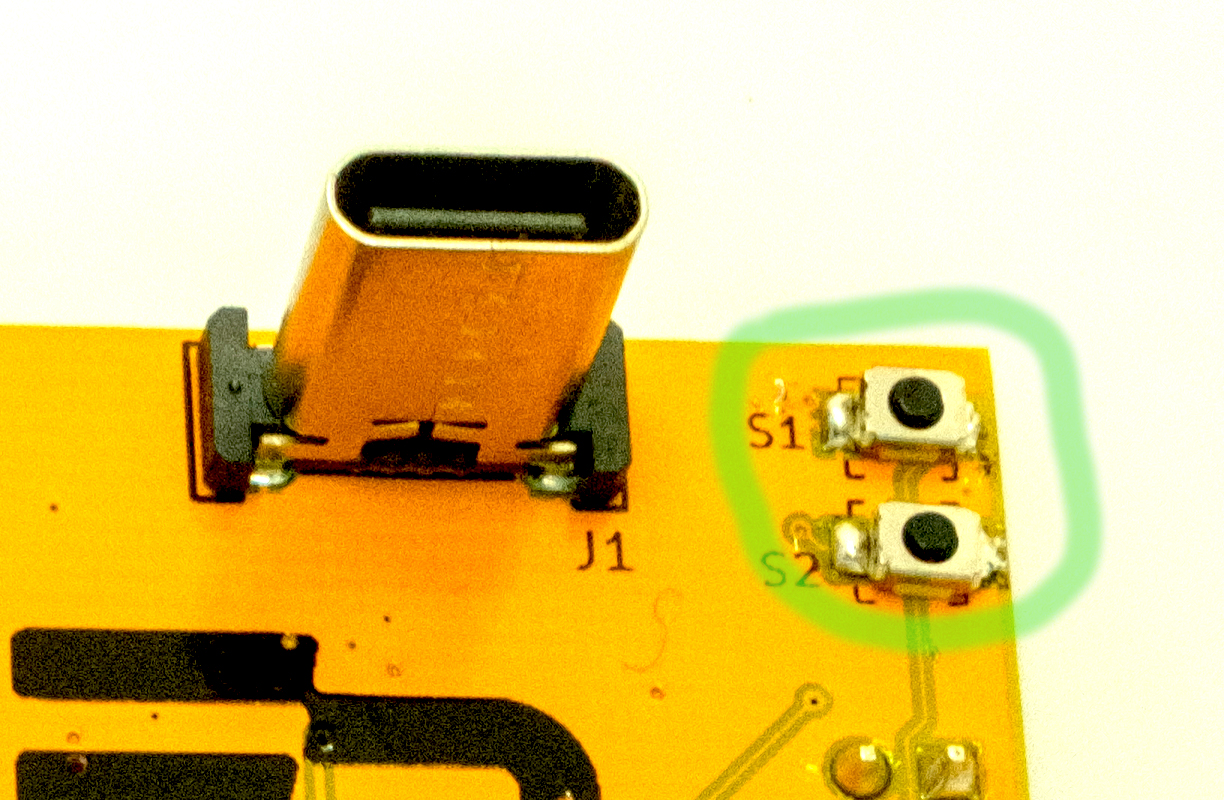
Step 2: Reset and boot select buttons
On the front size of the board, add on the two buttons. These are surface mount buttons. The pads are pre-tinned. A good technique is to melt the solder on one side and slide the button in, then press down on the other side with the soldering iron to melt the solder on the second pad. You don’t need any sort of specialist iron from this, but keeping the temperature low (350C) might be useful, as high temperatures can melt the plastic in these buttons.
If you’re doing SMT for the first time, this is probably a good beginners first step, with a large component. Here’s a video that might help:
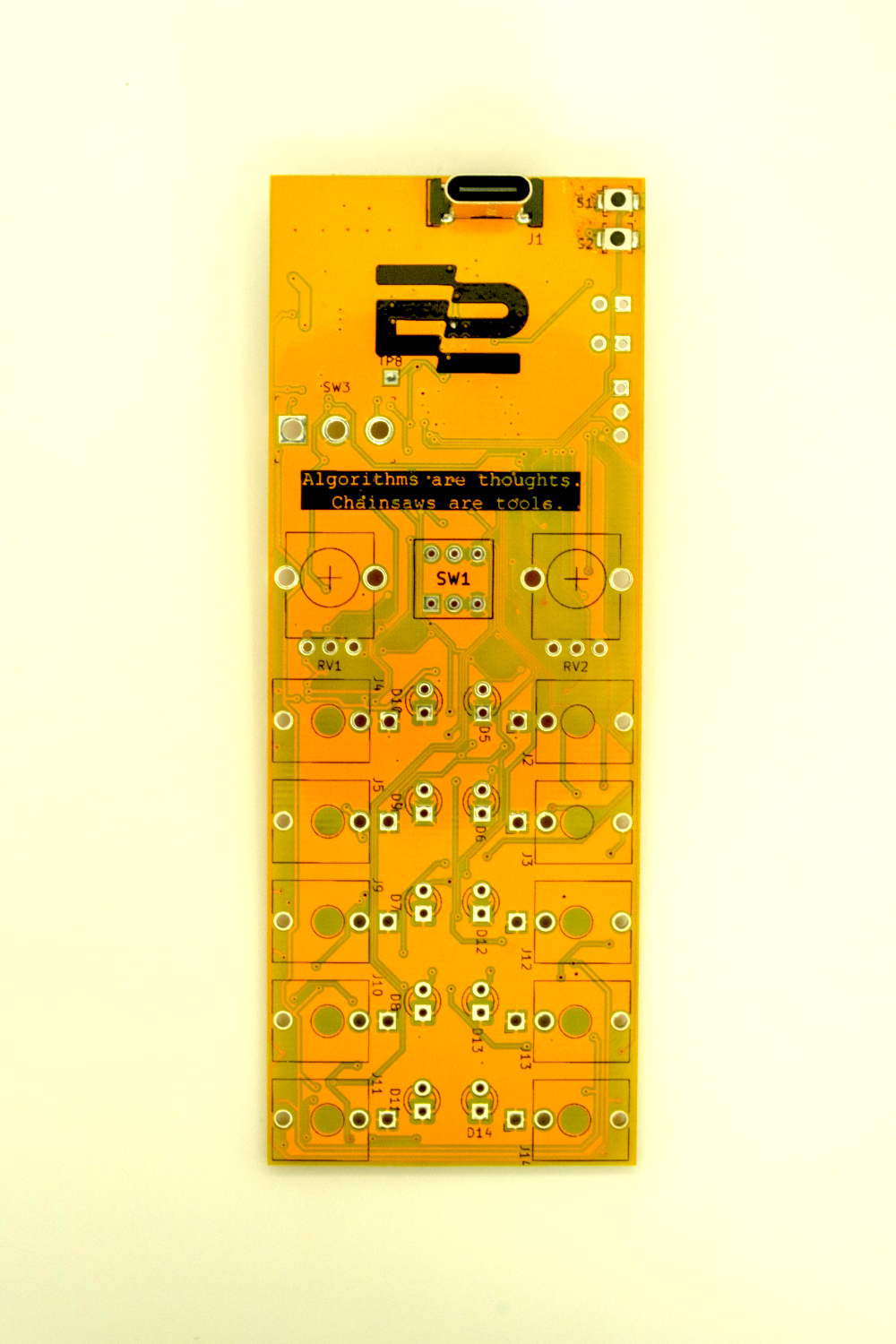
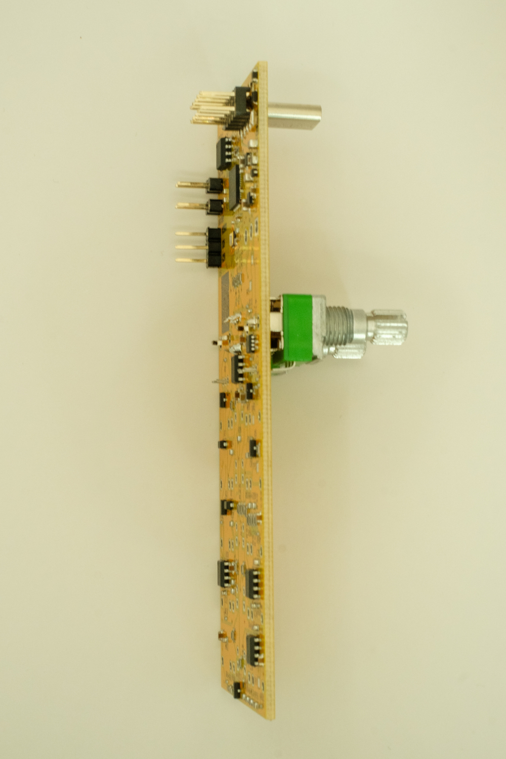
Step 3: Place (but don’t solder) potentiometers
Push the two pots into the board
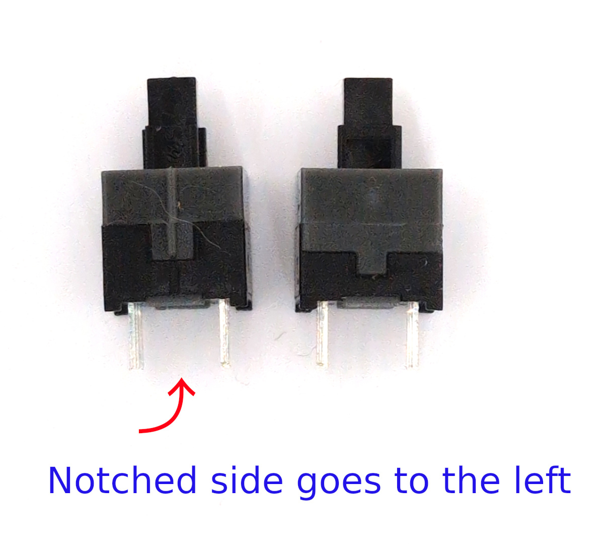
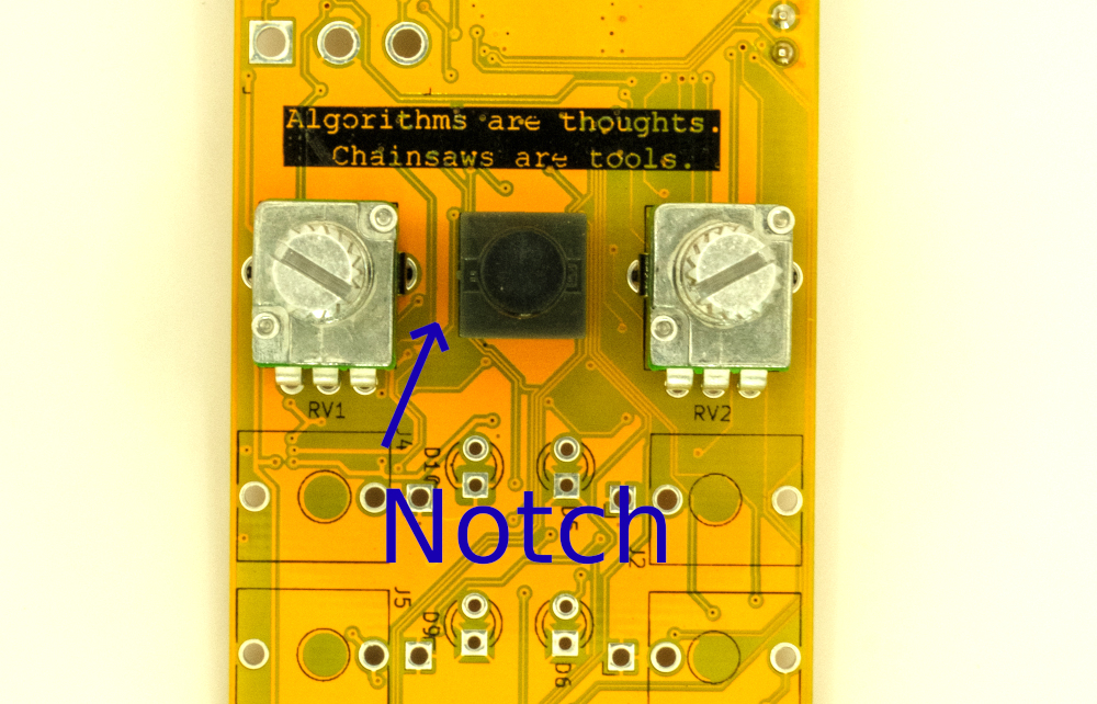
Step 4: Place (but don’t solder) the momentary button
Important: this is a polarised component. You can see notch on one side, this needs to go to the left of the PCB.
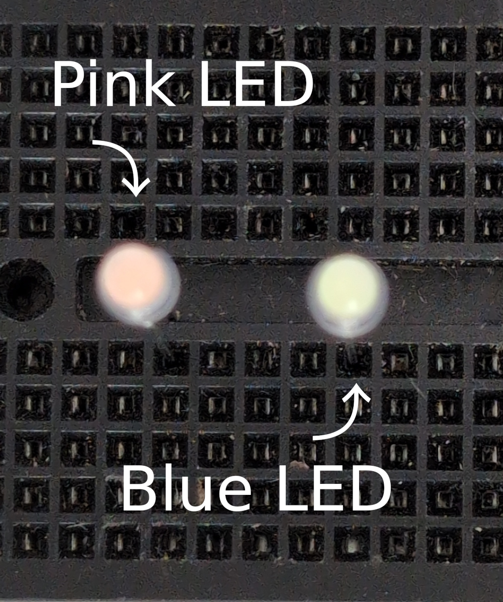
Step 5: Mount LEDs (don’t solder yet)
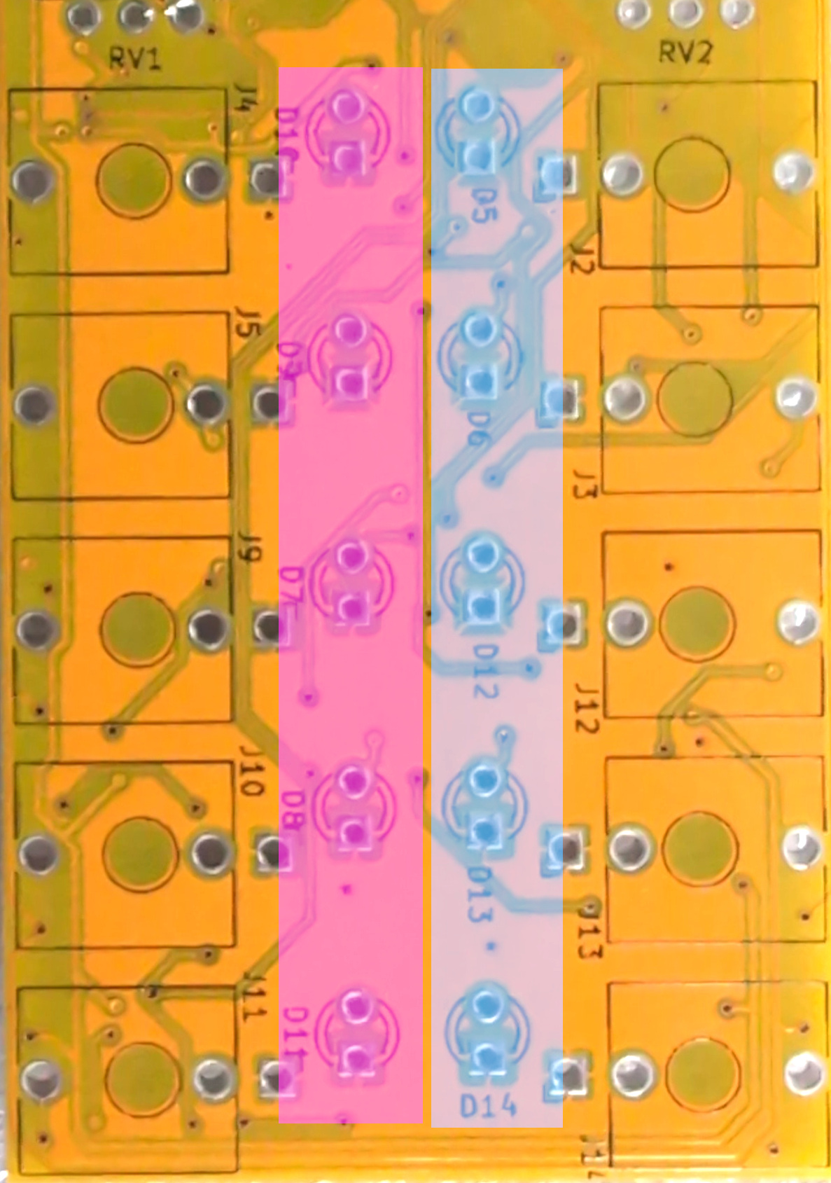
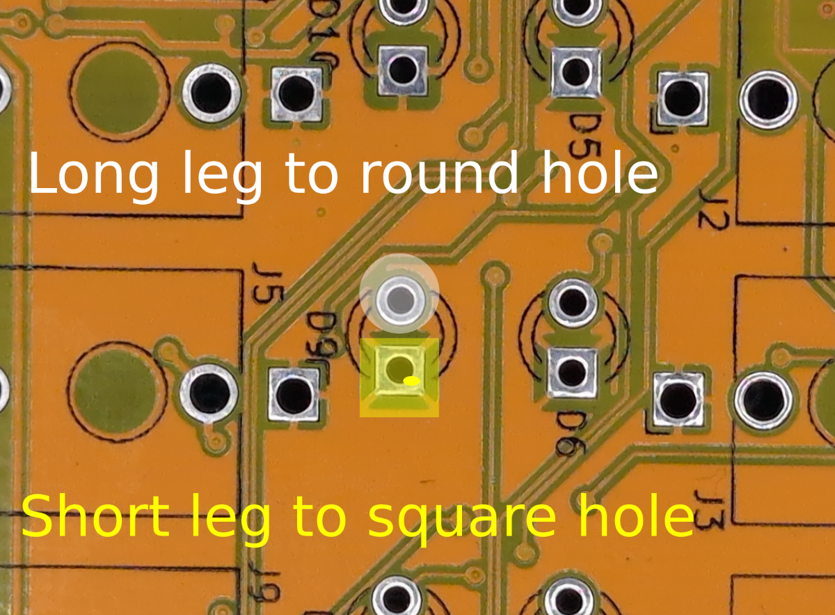
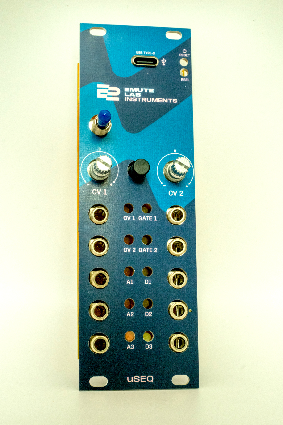
Five pink LEDs go on the left hand side in D7-11. Five blue LEDs go on the right hand side in D5,6,12,13,14. The holes with square pads are ground (short leg). To tell the pink and blue LEDS apart, look down on them from the top, in clear light.
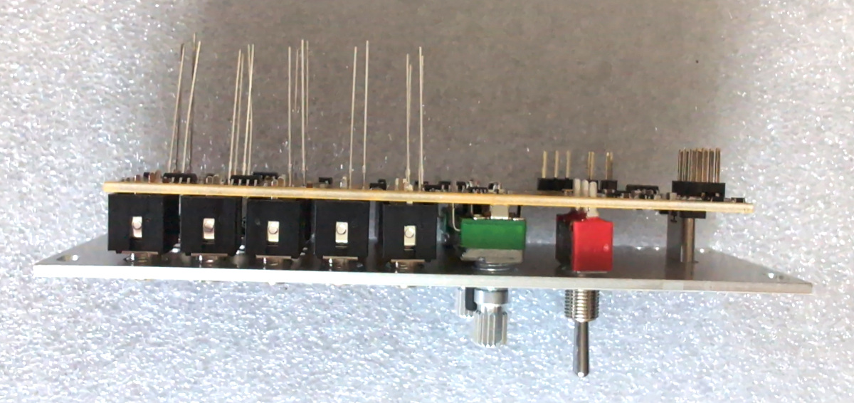
Step 6: Place sockets and switches (still don’t solder)
Probably best to put the sockets in place first. Double check that all pins are in the holes when you’re done.
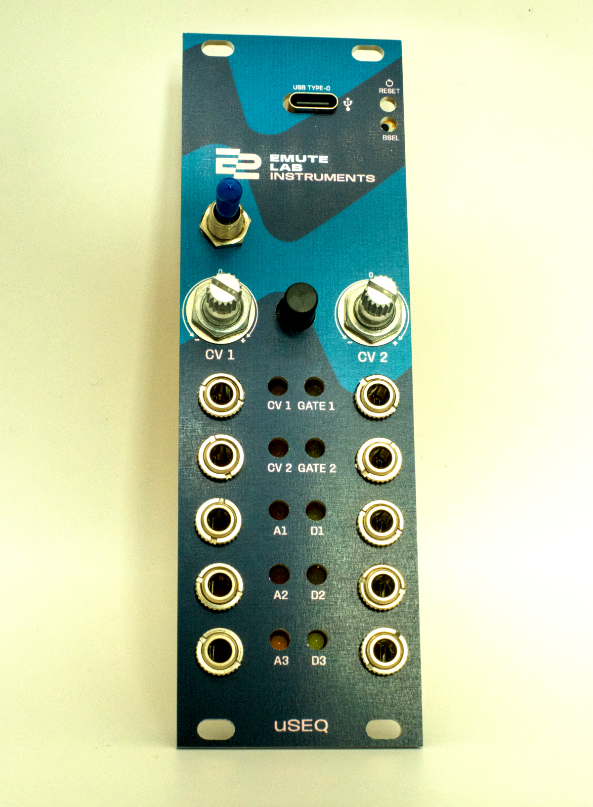
Step 7: Put on the face plate
Shake it around a bit until things fall into place
Step 8: Loosely put the nuts onto the switches, pots and sockets
Step 9: Solder the momentary switch.
This is a good time to double check that everything is in place properly before you solder.
First solder the momentary button. Important: make sure that it’s pressed fully flat against the PCB when you solder, otherwise it might sit at an angle and rub against the faceplate.
Step 10: Solder sockets, pots and switches (but wait on the LEDs)
It’s probably easiest to start with the big stuff the pots and toggle switch, then go down each side and do the jack sockets.
Step 11: Check LED positioning
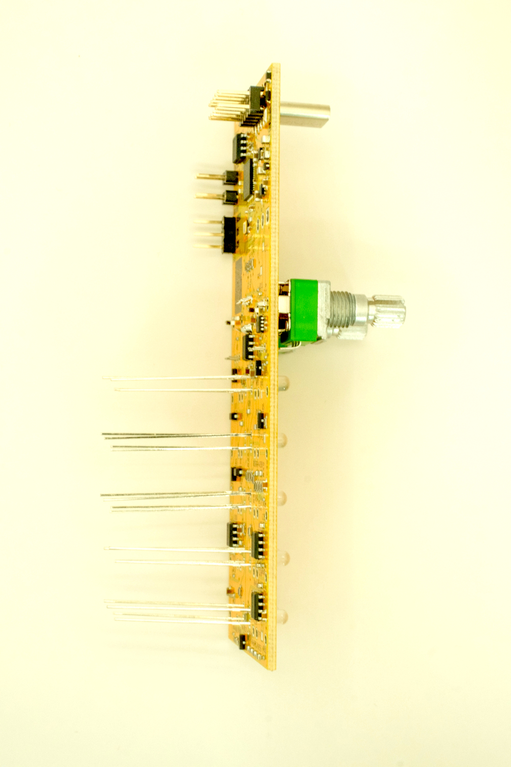
It’s really hard to desolder the LEDs, so make sure they’re in position before you solder. Hold up the module and look at the underside, move them into position so they’re sitting in the panel holes, and put the module down carefully on the desk.
Step 12: Solder the LEDs
To be sensible, check after you’ve done half of them that nothing has been knocked out of place.
Step 13: Clip the LED legs
Step 14: Tighten the nuts on the front panel
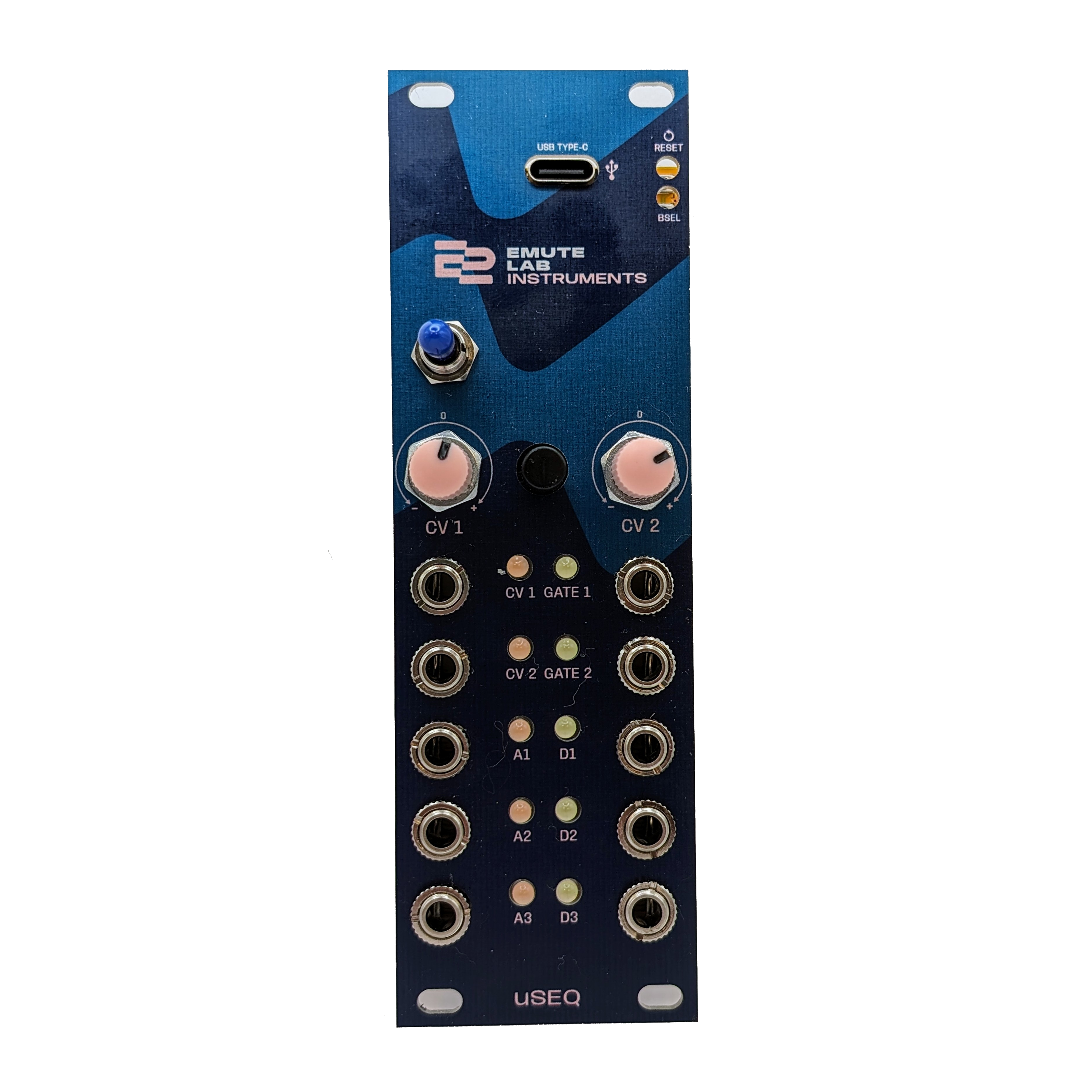
Step 15: Place the potentiometer covers, toggle switch cover and momentary switch cap
Testing
There’s no calibration required. To test the module, try running the code in the getting started guide.